See Diagram B to determine the proper mounting clamp direction. The VDO Generator Sensor is Part #3001. View and Download VDO TACHOMETER installation manual online.

All VDO Programmable Tachomelers with Hanni-teler ieature auio- . Proper wiring of the VDO Programmable Tachometer with typical ignition systems. VDO North America warrants all merchandise against defects in factory workmanship and materials for a. INSTRUCTIONS FOR THE INSTALLATION OF THE TACHOMETER ARE CONTAINED. During installation, ensure that the product’s components do not affect or limit vehicle functions.
Only connect cables according to the electrical wiring diagram. Electronic Tachometer with LCD Engine Hour Meter, 0-515-012-037.
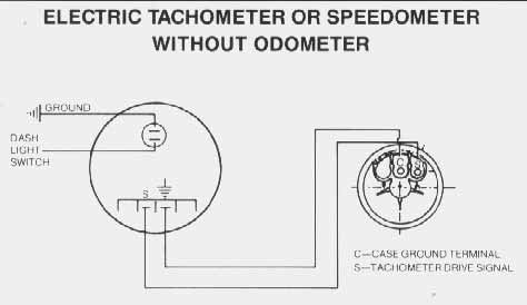
THE INSTRUCTIONS FOR INSTALLATION AND ELECTRICAL WIRING FOR THESE TACHOMETERS FOLLOW. Find your application in Diagram A and set the. Anyway, if you have an VDO tach install instruction sheet, or have one. The ‘wiring diagram shows a on the side that connects to the . Electronic Speedometer Mk- General Wiring Diagram.
Electronic Tachometer – Wiring Diagram Calibration . VDO cockpit vision VDO cockpit international i VDO Kienzle.

Wire the tachometer to the vehicle as shown in Diagram. Electrical Wiring Troubleshooting electrical problems. My VDO tach has a green, re white, black, and blue wire.
VDO Wiring Diagrams – Diagram will open in a new window.